Complete System
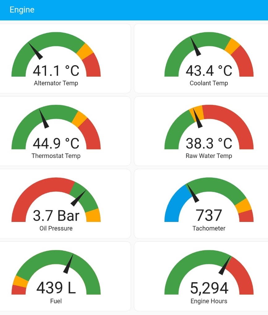
Build a complete engine-monitoring dashboard with 8 gauges: 4× Temperature (DS18B20) + 1× Tachometer (RPM) + 1× Oil Pressure + 1× Fuel Tank Level + 1× Engine Hours. All sensors feed a single ESP32 running ESPHome, visualised in Home Assistant.
- 4× Temp gauges
- 1× Tachometer
- 1× Oil pressure
- 1× Tank level
- 1× Engine hours
As featured in PBO:
How I installed a smart engine monitoring system on my sailboat
.
🧭 What You’ll Build
- One ESP32 “remote hub” that reads multiple sensors (1-Wire, I²C, pulse) in the engine bay
- 8 total gauges: 4× temperature (raw-water elbow, alternator, coolant area, thermostat), 1× tachometer (RPM), 1× oil pressure, 1× fuel tank level, 1× engine hours
- Color-coded needle gauges, history trends, and alert automations (siren/horn/notifications)
- A scalable pattern to add more sensors over time (additional DS18B20s / INA219s)
🧩 System Architecture
- Sensors → ESP32: DS18B20 (1-Wire), INA219 (I²C), alternator tacho via optocoupler (pulse)
- Firmware: ESPHome on the ESP32 (OTA updates)
- Backend: Home Assistant on Raspberry Pi (entities, templates, dashboards, automations)
- Power: 12 V → 5 V DC-DC buck to ESP32; 3.3 V rails for sensors
💡 Practical wiring pattern
- Use a screw-terminal breakout for the ESP32 to make engine-bay wiring robust
- Route all DS18B20s to a single data pin with one 4.7 kΩ pull-up
- Put INA219s on SDA
GPIO21/ SCLGPIO22; up to 8 per ESP32 with unique addresses - Feed alternator W/stator/tacho to a 24 V optocoupler module → ESP32
GPIO25(pulse counter)
🧰 Consolidated Parts & Tools
- ESP32 dev board (30-/38-pin) + screw-terminal breakout/enclosure
- DS18B20 waterproof probes (1–5+ as needed) + 4.7 kΩ resistor (single pull-up for the bus)
- INA219 modules (for oil sender & fuel sender; supports more tanks/senders)
- Optocoupler input module (24 V recommended) for alternator tacho
- Wiring: Dupont leads, double spade adapters, cable ties, strain relief
- Power: 12 V → 5 V DC-DC buck (boat install) or USB (bench)
- Optional alert devices: siren/horn, lights; optional relay for alternator cooling strategy
🚀 Build at a Glance
- Provision an ESP32 in ESPHome; confirm OTA and logs work.
- Add modules one by one:
- DS18B20 temperature bus on
GPIO25with 4.7 kΩ pull-up → discover addresses (aim for 4 probes → 4 gauges) - INA219 on I²C (
SDA 21,SCL 22) → read sender voltage (oil & fuel) - Optocoupler from alternator W/stator/tacho → ESP32
GPIO25pulse counter
- DS18B20 temperature bus on
- Use the YAML snippets for each module (links below).
- Calibrate (voltage→pressure, voltage→% full, pulses→RPM) using your engine’s values.
- Create HA dashboards (needle gauges, severity bands) and add alert automations.
🧱 Modules (Start Here → Then Open Each Full Guide)
Engine Temperature (DS18B20)
- 4× temperature gauges (raw-water elbow, alternator, coolant area, thermostat)
- 1-Wire bus on
GPIO25, 4.7 kΩ pull-up - HA gauges + alternator > 100 °C alert
Oil Pressure (INA219)
- 1× oil-pressure gauge (volts → bar, two-point calibration)
- Tap sender “Gauge” terminal →
INA219 VIN+ - I²C:
SDA 21,SCL 22
Digital Tachometer (Optocoupler)
- 1× tachometer gauge (pulse counter → RPM)
- Alternator W/stator/tacho → optocoupler → ESP32
GPIO25 - Includes:
engine_hours(counter); optionalengine_active
Fuel Tank Level (INA219)
- 1× tank-level gauge (volts → % full)
- Sender “Gauge” terminal →
INA219 VIN+ - ESPHome exposes Tank Sender Voltage; HA template maps volts → %
📎 Series links (quick list)
📟 Dashboards & Automations
Gauges
- Total: 8 gauges → 4× temperature + 1× oil pressure + 1× RPM + 1× tank level + 1× engine hours
- Temperature gauges (needle) with severity: e.g., yellow 30 °C, red 42 °C at the raw-water elbow
- Oil pressure 0–5 bar (needle), green ≈ 3, yellow 4, red 0
- RPM 0–2400 with idle/amber/red bands
- Fuel level 0–100 % with low-fuel alert
- Engine hours counter (display card)
Automations
- Alternator > 100 °C → siren; optional relay to reduce field current
- Low oil pressure → horn/notification (gate by
engine_active) - Overspeed (RPM > threshold) → alert
- Low fuel (%) → notify before departure
History & Insight
- Compare last week’s engine temps to learn “normal” operating ranges
- Track oil pressure vs. RPM to spot wear or viscosity issues
- Correlate fuel usage with typical cruise RPM
🛠️ FAQs & Troubleshooting
DS18B20 shows as “unknown”
- Copy the discovered address from logs and replace the placeholder in YAML; check the 4.7 kΩ pull-up and bus wiring
INA219 reads 0.0 V
- Confirm I²C pins (
SDA 21,SCL 22) and that VIN+ is on the sender’s “Gauge” terminal
RPM unstable
- Verify alternator W/stator tap, optocoupler polarity, grounds; add another calibration point; keep wires short
📰 Featured by PBO
Read the Practical Boat Owner article covering this end-to-end project:
Then return here and follow the modules above to build your own system.
⚠️ Disclaimer
The information provided is for educational and informational purposes only. Perform all installations safely and correctly; consult a licensed professional for boat electrical work. Use at your own risk.