Precision Voltage Measurement with the INA219
Introduction
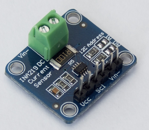
In the world of smart boating, accurate monitoring of electrical parameters is crucial for ensuring the reliability and efficiency of your vessel’s systems. One key component that can help achieve this is the INA219 board, a high-side current sensor that can measure both the bus voltage and the current flowing through a load. This article will guide you through connecting the INA219 to an ESP32, configuring it using ESPHome, and understanding its advantages over traditional voltage dividers.Why Choose the INA219?
The INA219 is a versatile sensor capable of high-precision measurements of both voltage and current. Unlike traditional voltage dividers, which can be complex to set up and may introduce errors, the INA219 offers a plug-and-play solution. This makes it an excellent choice for smart boat applications where reliability and ease of use are paramount.Components Needed
- INA219 board
- ESP32 microcontroller
- ESPHome for configuration
- Connection wires
Powering the INA219
The INA219 board will be powered by the 3.3V output from the ESP32, simplifying the power management aspect of your setup. This ensures that the sensor operates within its optimal voltage range, providing accurate readings.Connecting the INA219 to the ESP32
Connecting the INA219 to the ESP32 is straightforward. Here’s a simple wiring guide:- VCC to 3.3V: Connect the VCC pin of the INA219 to the 3.3V output of the ESP32.
- GND to GND: Connect the GND pin of the INA219 to the ground pin of the ESP32.
- SDA to SDA: Connect the SDA pin of the INA219 to the SDA pin of the ESP32.
- SCL to SCL: Connect the SCL pin of the INA219 to the SCL pin of the ESP32.
Advantages of Using the INA219
- Accuracy: Provides precise voltage and current measurements.
- Ease of Use: Simplifies the setup process with plug-and-play connectivity.
- Versatility: Can measure high-side currents, making it ideal for monitoring various electrical systems on a boat.
How Many INA219s Can You Connect to an ESP32?
The ESP32 microcontroller supports two I2C buses, which significantly enhances its capability to connect multiple I2C devices. By utilizing both I2C buses, each INA219 sensor can maintain its default or set I2C address, thus allowing for more sensors to be connected simultaneously.I2C Buses and Pins on ESP32
- I2C Bus 1 (Default):
- SDA (Data) pin: GPIO 21
- SCL (Clock) pin: GPIO 22
- I2C Bus 2:
- SDA (Data) pin: Customizable (commonly GPIO 18)
- SCL (Clock) pin: Customizable (commonly GPIO 19)
Addressing and Connecting Multiple INA219 Sensors
Each INA219 sensor can be configured with one of four possible I2C addresses: 0x40, 0x41, 0x44, and 0x45. By utilizing both I2C buses, you can connect up to four INA219 sensors on each bus, each with a unique address. This setup allows for a total of eight INA219 sensors connected to a single ESP32. Here’s the breakdown:- I2C Bus 1: Connect up to 4 INA219 sensors with addresses 0x40, 0x41, 0x44, and 0x45.
- I2C Bus 2: Connect another set of 4 INA219 sensors with the same addresses (0x40, 0x41, 0x44, and 0x45).
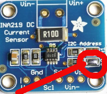
How to Change the INA219 Address
To change the I2C address of the INA219 sensor, you need to adjust the solder jumpers on the board. The INA219 has three address pins: A0, A1, and A2, but typically only A0 and A1 are used to change the address. Here’s how you can set them:- Default Address (0x40): A0 = 0, A1 = 0
- Address 0x41: A0 = 1, A1 = 0
- Address 0x44: A0 = 0, A1 = 1
- Address 0x45: A0 = 1, A1 = 1
- Locate the Address Pins: Find the A0 and A1 solder pads on the INA219 board.
- Solder the Jumpers: Use a soldering iron to bridge the solder pads as per the desired address configuration.
- For example, to set the address to 0x41, solder the A0 pad and leave the A1 pad open.
- Verify the Address: Ensure that the solder connections are secure and that there are no shorts between the pads.
⚠️ Disclaimer
The information provided is for educational and informational purposes only. Perform all installations safely and correctly; consult a licensed professional for boat electrical work. Use at your own risk.
Conclusion
Integrating the INA219 with an ESP32 provides a robust solution for monitoring electrical parameters on your smart boat. By leveraging ESPHome for configuration, you can ensure accurate and reliable data collection with minimal setup. Whether you’re monitoring battery voltage, solar panel output, or other critical systems, the INA219 offers a straightforward and effective approach. With the ability to connect multiple sensors, you can scale your monitoring system to meet the needs of your vessel, ensuring a safe and efficient boating experience.